Why would anybody want a hornsystem in his home, these things are really big and rather hard to position in a normal living-room. Besides that they are difficult to design, they are difficult to copy and you may end up with a system colouring your sound.
Despite of all it's disadvantages I'm a great fan of the horn systems. Not particularly for high- and midrange, but certainly for the low frequencies. Until today I've not met any "conventional" speakersystem that equals the performance of a bass horn!
The horn:
Until now I've stated some major drawbacks of the horn. Has this system any advantages? Let's start with the disadvantages:
-
For a good job they tend to be really big
-
Specific designs need to be placed in a corner, not everybody has the possibilities
-
Bad designs colour the sound too much
-
Difficult to design and/or to copy in comparison to "conventional" systems
-
The bandwidth is relatively small
But now the advantages!
-
Very dynamic and articulated bass performance
-
Very low distortion
-
Excellent impuls behaviour
-
High efficient and so easy to drive...
You may end up asking yourself; is this all there is? On paper it seems a more or less laborious system, but once you listen to a well designed horn, you are hooked! The performance pulls you into the music.
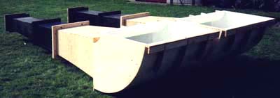
The final design:
I already made it clear that I'm a fan of horns, but how far can you go with these systems? With a lot of courage and some knowledge about what a horn can do I started (1985!) calculating the possibilities for my first "big" design. Finally, after two weeks, I finished the job. The calculated and practical data of my subhorns were:
Fc = 23,7 Hz, L = 3.67 m, Ah = 0,0354 m², Am = 0,8569 m², k = 0.8683
Quite a birth actually, for a twin ! The shape is stretched with only one curve at the end. I buried both horns underneath the floor of my listening-room, only the exits remain visible.
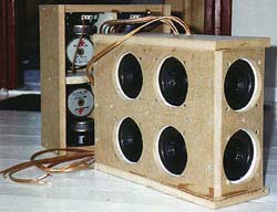
Both hornexits (two channels) lie close together, which enables a good response of 32 - 150Hz (+/- 3dB). The used units at that moment were cheap and small Monacor SP60 chassis, 8 (!) per channel (two ranks of 4 parallel, both ranks serial because of the impedance). I chose these units because I wanted fast, small and inexpensive devices, the amount was required to adapt the total conus-surface to the hornneck for maximum efficiency.
A theory © :
Is was not easy at all to determine the optimum shape of the horn for a specific speaker chassis. It is very convenient to know what the horn will do before you build one. It took me quite some time experimenting with models and formulas in finding the applicable ones for the hornshape, the needed mouth area and the volume of the closed cabinet in front of the horn. Weeks of sweating over A4 size formulas with a fair amount of abacadabra. The formulas supplied in this article were extracted from the abacadabra and can be used to calculate the major points, which will do unless you want to prove the theoretical principles of the horn.
To be able to calculate a horn you first need the following data of your speaker chassis:
Before continuing we need to know whether or not the chosen unit is suitable for the design. The higher the Qts the smaller the usable bandwidth will be. This can be calculated by formula:
and:
The calculated values roughly indicate the range within the chassis can be used as driver for a bass horn. When this data is usefull for a horn we can determine the throat area Ah (m²) with the next formula where (c = 340m/s):
Note: all formula's mentioned below only hold on the calculated throat area Ah !!
Okay, that's done, now we only have to calculate the track from Ah to Am. To do this we need the following data:
The picture explains the "flair" T
The formula:
where Ax (the calculated surface (m²), Ah (the throath area (m²), x (the distance from Ah (mtr.), xo (2 / k) and T (a variable that determines whether the horn is exponential (T=1) or hyperbolic (T <1) of shape). When you decide to build a common exponential horn then the last formula can be simplified to:

Now the exponential horn shows lower efficiency (and acoustic output) around its resonance frequency compared to the hyperbolic variety. The distortion, however, is less. Assuming that the horn is of infinit lenght and the wavelength "fits" the horn then the mouth area Am must comply to formula:
The outcome is true when the horn is located in free air, but this is not likely to be useful in a normal room, we can happily devide the outcome by 2 (when the horn's exit is placed on the floor), by 4 (when the horn's exit is placed on the floor and against a wall) and by 8 (when the horn's exit is placed in a corner). The floor and walls are an extention of the horn! This is the reason why Klipsch and ACR designed their horns for corner loading. Its perfect for the lower frequencies, but usually not above 300Hz.
A horn does not have a radial behaviour but a more directive one. A common speakersystem has a radial behaviour and sounds best with free space around it (did you ever listened to a "conventional" speaker placed directly in a corner?).
Additional info to take into account:
Until now only a small part is explained, there is more to it! Now we mainly know how to calculate the actual horn it is useful to know how two horns beside each other have influence on the response, and how the driver cabinet (the back chamber) has influence on the speakers parameters when adapted to the horn.
When the mouth area Am of two horns are placed beside each other then the result will be a better performance in the lowest bass because the area is now doubled. The next formula can be used to see if we can lower the frequency Fg by the enlargement of Am.
Mind in the calculation where you want to place the horn, by placement in the corner the surface Amt must be multiplied by 8 !
An advantage is that the new horn can be calculated as being shorter. Because we work in stereo the efficiency is 6dB higher (two speakers instead of one) and the power capabilities (mechanical and electrical) improves.
What has changed is the larger (total) throat area Ah. In reverse you could say its the smaller (half) mouth area Am. The bigger the throath- or the smaller the mouth area the shorter the hornlength.
Suppose a Fg of 30Hz is wanted, according to the next formula the mouth area Am (m²) will be:
Placed in a corner the result will be 1.32 m². When two horns with their mouth close to eachother are used, the result can be divided by 2 (0.658 m²). By calculating the contour (flair) of the horn it becomes clear that for the same Fg a shorter horn is sufficient. Of course it is possible to use more than one speaker in a horn, Ah is then multiplied by the amount of speakers.
The advantage of more speakers is that the power (mechanical and electrical) improves, the throath can be enlarged (shorter horn) and, not less importent, the speaker selection is less critical.
The back chamber:
A front loaded horn design needs a closed space behind the speaker for proper loading down to Fg. Its volume can be changed to adapt the horn to different speakers.
The back chamber volume Vb to be used with the calculated horn can be determined in order to optimize the speaker to the hornneck and given proper loading down to Fg. Take into account that Vas and Vb are in dm³ and m³.
When Vas is smaller then Vb use formula:
The compression chamber:
Finally there is a possibility to create a compression chamber (Vf) between the driver and the throat (Ah) of the horn.
The volume of the compression chamber works like a low-pass filter (6dB/oct.), the higher the frequency the higher the attenuation. The crossover point (-3dB) can be calculated with formula:
Vf is the volume. Note that a larger volume lowers the crossover frequency. The nice thing of these acoustical filters is that the output can be corrected without the use of extra electronics.
Another -3dB "filter" frequency is due the driver moving mass corner of the driver according to the formula mentioned before (Fh).
When you decide to build your own hornsystem, I strongly advise an exponential design with the largest possible horn mouth. The used speaker unit(s) requires a strong magnet (Qts <0.3) to be able to drive the air in the horn. The early decline in the lower frequencies can be corrected actively which works well in the area where the horn is active (>Fg).
My Sources:
Design Factors in Horn-Type Speakers. Daniel J.Plach (October 1953) from "An anthology of articles on loudspeakers from the pages of the journal of the Audio Engenineering Society".
Low-Frequency Horn Design using Thiele/Small driver parameters. D.B.Keele jr.. Preprint of the Audio Engeneering Society.
 Aktive emner
 Brugere
 Søg
Søg Emne: Hjørne horn


 det er desværre ikke særlig stuevenligt

 . Hjørnet vil desuden ofte forlænge hornet i sig selv - tænk på hjørnet som en tragt.
 jeg glemte lige at der også findes bagladehorn med store enheder, men det er ikke så typisk

 .
.
